OTC Rental
Do you have a plan if your air compressor breakdowns or your facility needs temporary or long-term support?
Make OTC Rental a part of your plan!
OTC has an extensive fleet of Centrifugal oil-free air compressors, along with a diverse range of Rotary, Booster, and Blower products, to ensure your needs are met without the burden of capital expenses. Whether your compressed air need is an emergency, a temporary backup, or to amplify existing systems – OTC has the rental solution for you.
100% Oil-free Air
OTC compressors meet ISO 8573-1 Class Zero oil-free air. ISO 8573-1 standards define air quality levels and methods for determining contaminants in the air system. Class Zero is the industry standard in industries that require 100 percent pure air.
24/7 Remote Monitoring
OTC can provide remote monitoring that provides real time data on asset, system status, performance, and history anytime, anywhere through any web enabled device.
Support
With our Channel Partner Network we have resources throughout the US to assist with sizing, setup, installation and operating of equipment.
Out of the Box Solutions
With over 35 years’ experience, there’s no compressed air problem we can’t solve.
Air Compressor Rental Options
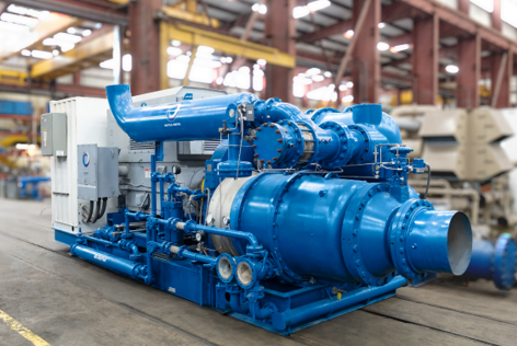
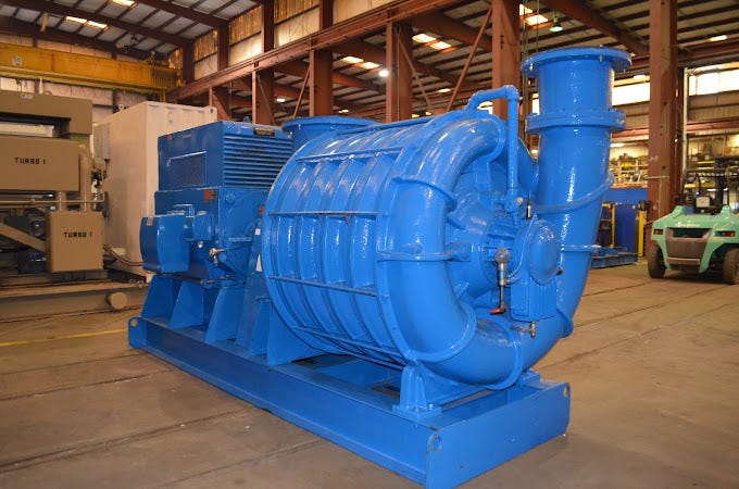
CENTRIFUGAL
Centrifugal Air Compressors provide customers with unique, attractive solutions for emergency, planned, and long-term air needs. These compressors can provide significant fuel savings and come in a wide range of capacities. Experience compact power with customizable pressures and discharge temperatures.
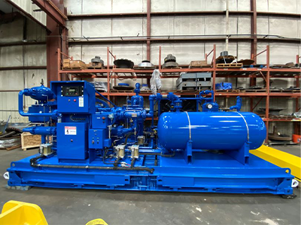
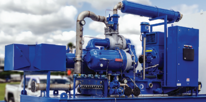
BOOSTER
Maximize your air potential with Booster Air Compressors, your solution for reaching optimal pressure levels. When pressure falls short, our boosters step up, enhancing low-pressure air for your tasks.
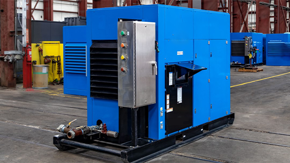
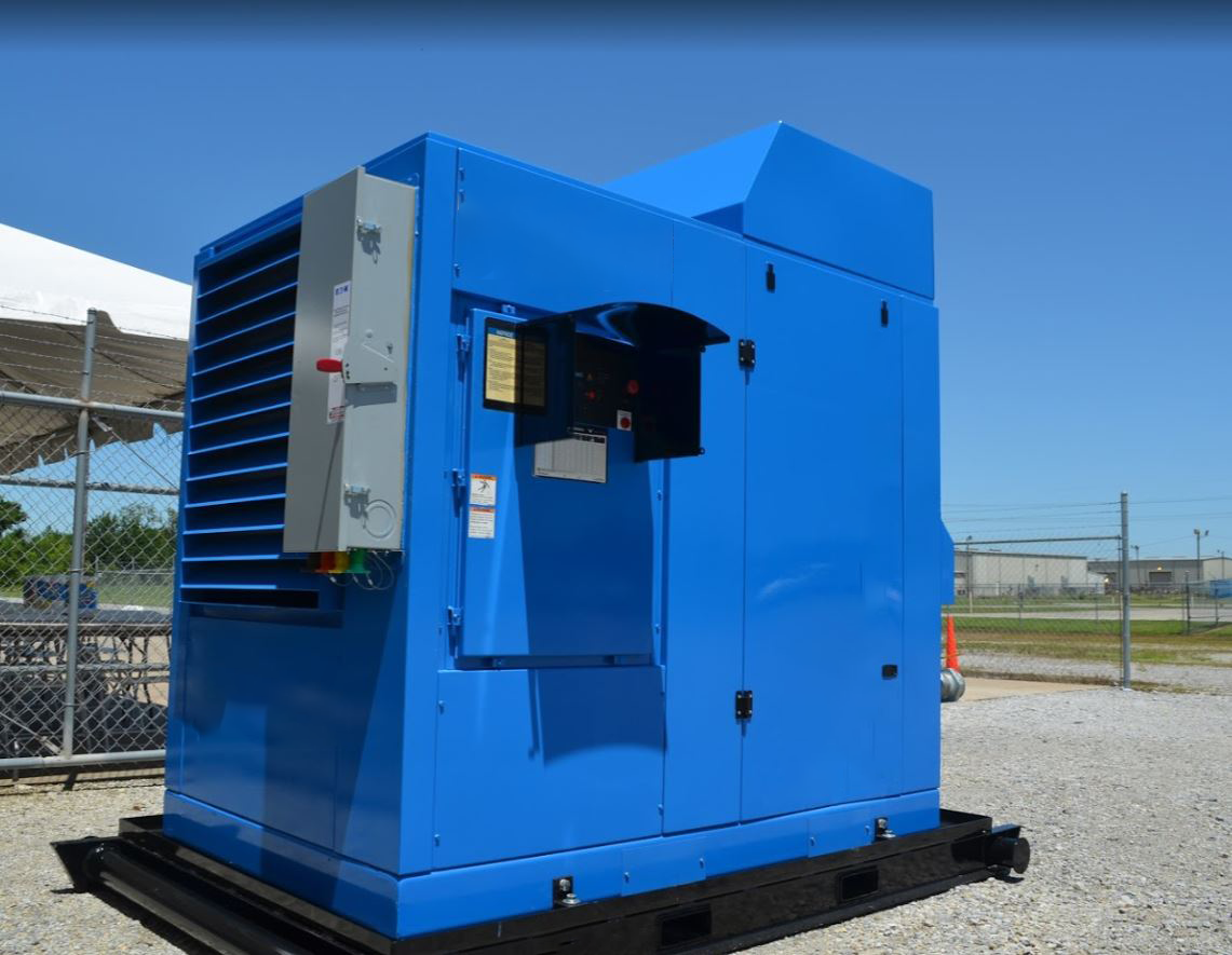
ROTARY
Experience the Evolution of Air Compression with Rotary Screw Oil-Free Air Compressors. Elevate your operations with a state-of-the-art solution that delivers unparalleled performance and reliability.
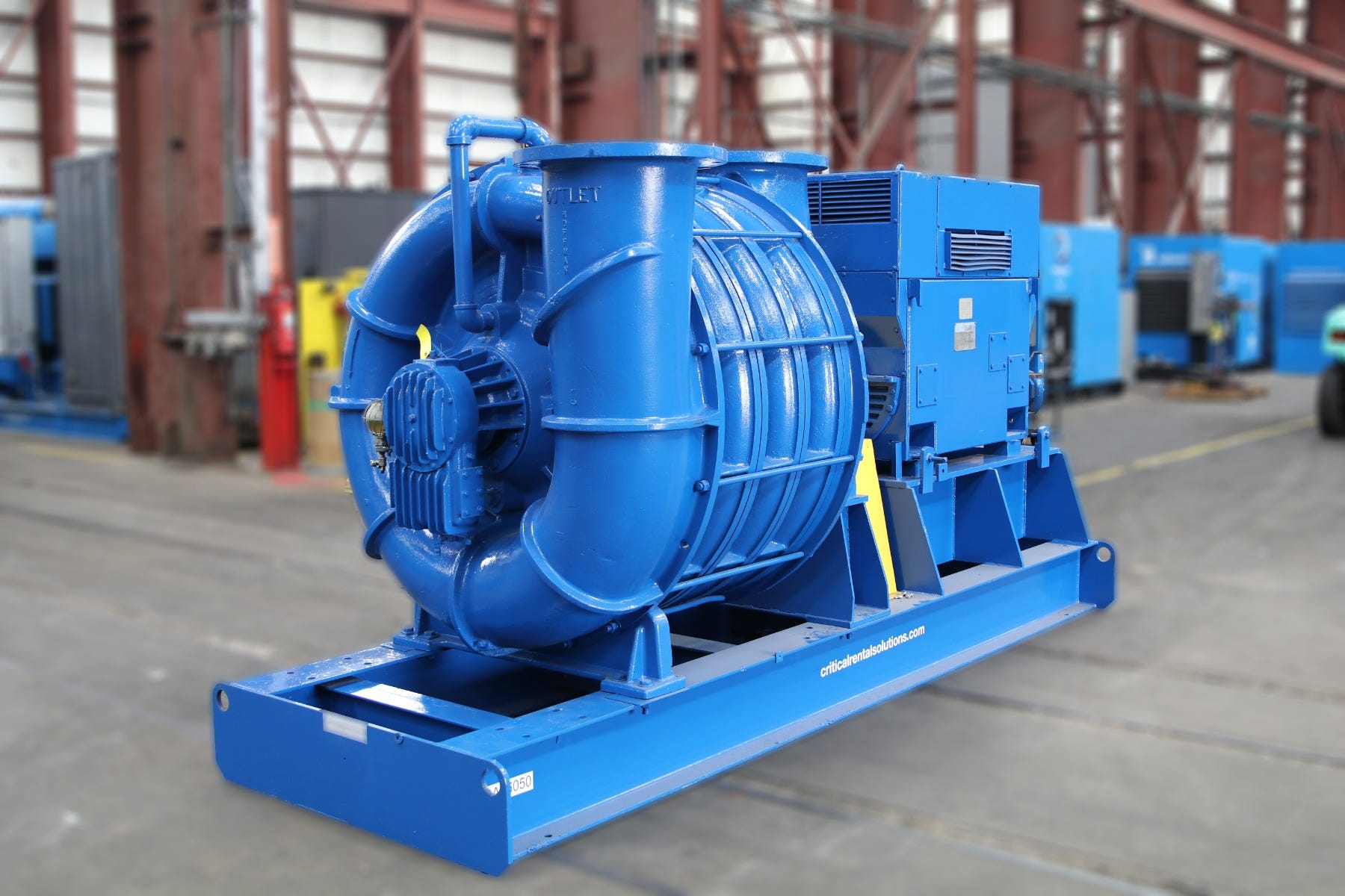
BLOWER
Enhance your air supply solutions with Air Compressor Blowers – the essential mechanical marvels for ensuring a continuous, low-pressure airflow. Unlike conventional compressors, our blowers guarantee unwavering air delivery without the need for high pressure.
Air Rental Solutions
Low Pressure
Vacuum to 25 psig
500 to 35,000 cfm
Rentals:
- Multi-stage Centrifugal PD
- Rotary Lobe Centrifugal Fan
Applications:
|
|
Nominal Pressure
Vacuum to 150 psig
100 to 35,000 cfm
Rentals:
- Rotary Screw
- Centrifugal
Applications:
|
|
High Pressure
Up to 650 psig
300 to 30,000 cfm
Rental:
- Reciprocating & Centrifugal
Applications:
|
|
ACCESSORIES
- Receiver Tanks to 6000 gallons
- Heatless Desiccant Dryers to 5400 cfm
- Water & Air Cooled After-coolers
- Motor Starters & Variable Frequency Drives
- Electrical Cable & Pneumatic Hose
Industry Insights
When to Rent: A Guide to Renting an Air Compressor
By OTC Insights Team on June 27, 2022
The Advantages of Renting an Air Compressor for Your Manufacturing Facility
By OTC Insights Team on June 27, 2022
OTC Invests in Solutions
By OTC Insights Team on May 31, 2022